Thermosyphon-based CCE architecture
About this page
This page was written by the New Horizons engineering team, which operated until December 2025. First-person references ("we", "our") are the original authors'. A number of those authors are now working with Phoenix GH, which maintains this material and stands behind it. Questions and comments are welcome — please get in touch.
Introduction and open licensing
New Horizons developed a thermal architecture for vaccine refrigerators that optimizes for thermal stability, energy efficiency, long hold time, and low-cost manufacturing. This architecture has been used in PQS-prequalified vaccine fridge models carrying the MetaFridge brand.
As of the date of this publication, 2025-07-28, Tokitae LLC has abandoned any pursuit of patent protection for the MetaFridge system and will not assert or enforce any patent rights related to this implementation. This dedication ensures that the community can freely use and build upon the system without restriction. This page, like most documentation on this web site, is licensed under the Creative Commons Attribution 4.0 International license, which allows permissive sharing, adaptation, and use (even commercially) with appropriate attribution. These US patent applications and their issued patents (and associated patents in other jurisdictions) are:
- Application 14/091,831, issued US9366483B2
- Application 14/484,969, issued US9726418B2
- Application 14/704,107, issued US9523522B2
- Application 15/219,592, issued US10260819B2
- Application 15/717,192, issued US10619916B2
System architecture overview
The defining characteristics of the thermosyphon-based heat transfer system are:
- A water/ice compartment containing a submerged refrigeration system evaporator located above the vaccine storage compartment. This water is frozen when the refrigerator has access to electricity, and during power outages is melted by heat carried from the vaccine compartment by the thermosyphon.
- A wickless thermosyphon which is thermally coupled to both the vaccine compartment and the ice compartment. This thermosyphon passively carries heat from the vaccine compartment to the ice tank using a common refrigerant as the active working fluid.
- Thermal insulation separating the ice compartment and the vaccine compartment. This insulation ensures that the temperature of the vaccine compartment is controlled by the thermosyphon physics, not the temperature of the ice compartment.
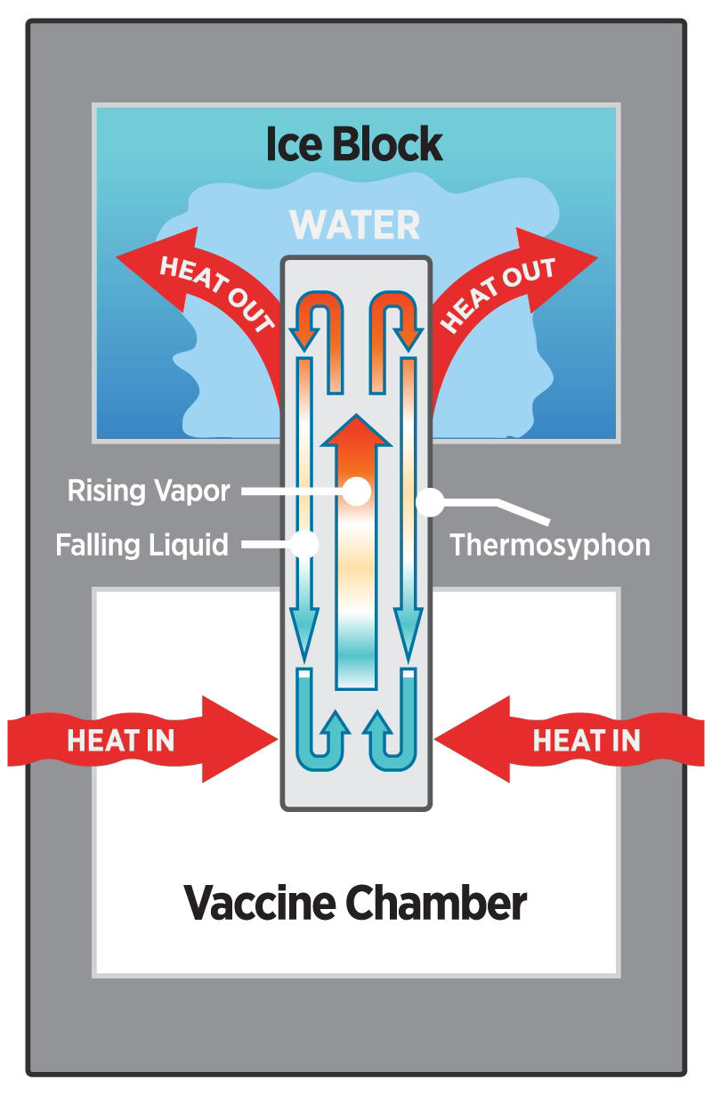
Figure 1: Thermosyphon basic operating principle
This architecture has several distinct advantages:
- Passive operation - The thermosyphon operates passively with zero energy for operation, active controls, or maintenance.
- Isothermal vaccine compartment - The thermosyphon works to minimize vertical thermal gradients, which means that the bottom of the vaccine storage compartment can commonly be held within 1°C of the top of the compartment.
- Space-efficient - The thermosyphon can be constructed using a roll-bonded aluminum panel. This means that the volume taken up by the thermosyphon itself is essentially negligible, which minimizes the insulated volume. Also, the overall volume of the refrigerator can be as small as possible for a given storage volume and holdover design profile.
- Inexpensive - The thermosyphon can be constructed using materials and manufacturing processes that are already ubiquitously used in the refrigeration industry.
- Energy efficient - by utilizing a submerged evaporator, the evaporating temperature can be very close to the water freezing point, which increases efficiency relative to CCE architectures that develop thermal gradients between the evaporating refrigerant and the water or other phase change materials that are being cooled.
Thermosyphon design and operation
Operating principle
The thermosyphon contains a mix of liquid and vapor refrigerant. The bottom of the thermosyphon surrounds the vaccine chamber. Heat in the vaccine chamber is transferred to the liquid refrigerant inside the bottom (evaporator) region of the thermosyphon. The liquid absorbs the heat, turns into vapor, and rises to the top (condenser) region of the thermosyphon. As the vapor rises, it is cooled by the ice block bonded to the top of the thermosyphon. As the vapor cools, it condenses back into a liquid, releasing its absorbed heat to melt the ice. Due to gravity, the liquid then falls back down towards the bottom of the thermosyphon to repeat the cycle.
An example thermosyphon design showing the various regions and components can be seen in the following figure:
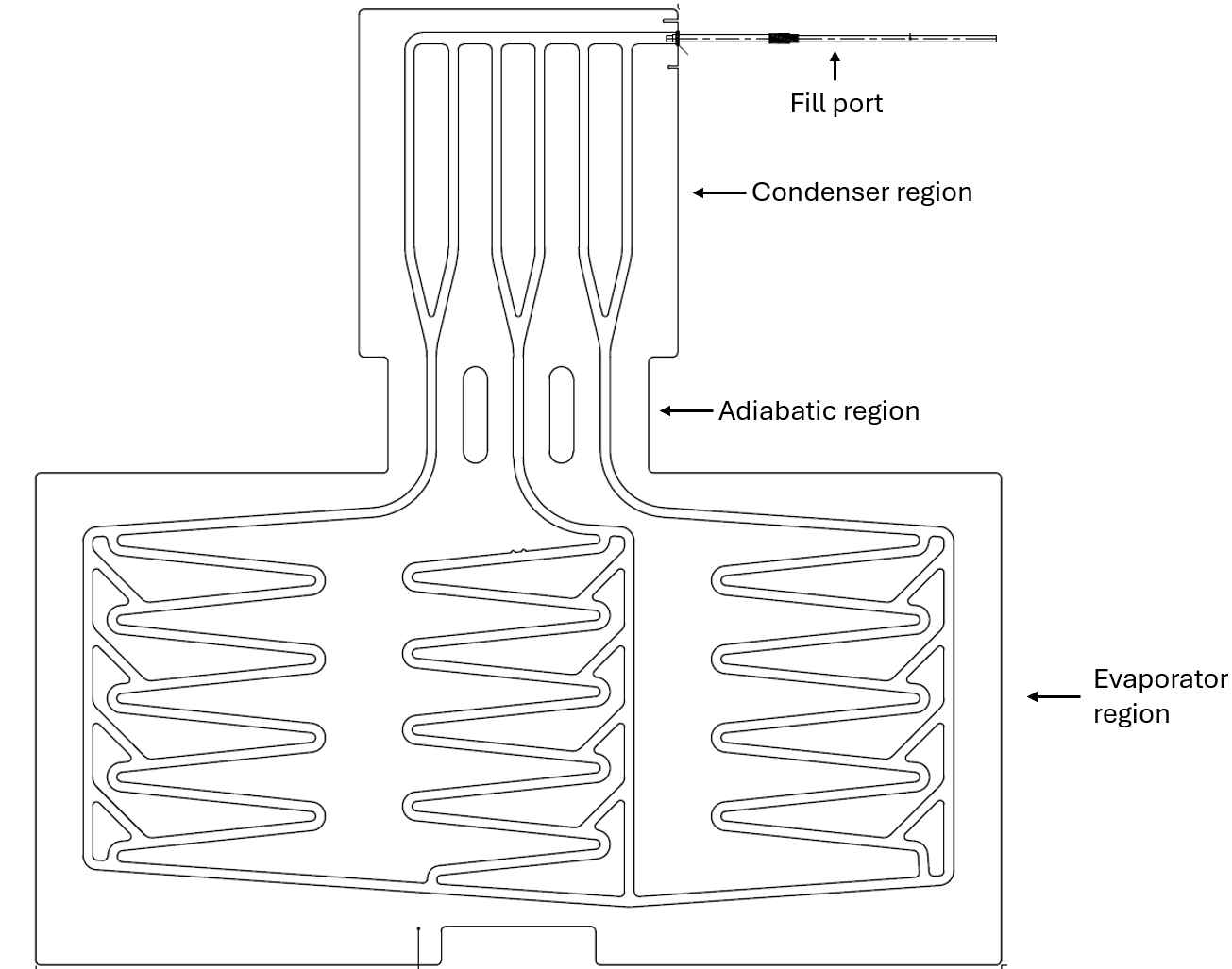
Figure 2: Thermosyphon components
In this example design, the top condenser region is thermally coupled via a sheet of thin double-sided tape to a metal ice tank (see Figure 6), and the bottom evaporator region is bent to wrap around the vaccine compartment. Thin double-sided tape sheet is also used to thermally couple to the plastic compartment liner.
Roll-bond construction
It is efficient to manufacture the thermosyphon using roll-bonded aluminum. Roll bonding is a refrigeration manufacturing technique used at scale for evaporators. This technique is completed by:
- Screen-printing a channel pattern on two sheets of aluminum
- Rolling the materials together at high temperature and pressure to weld them together on surfaces not covered by the screen printing
- Inflating the printed channel pattern to a specific thickness by injecting an ultra-high pressure gas while the welded plate is held between two flat surfaces that are separated by the intended resulting thickness of the design.
Roll-bond suppliers offer standard patterns, but custom designs are also possible. A custom design is required for this thermosyphon application and is cost effective. The long lead times for screen printing and manufacturing make iterative design challenging. To help potential implementers reduce required iterations, we have included a number of channel pattern design considerations in the “channel pattern design” section below.
To thermally couple the roll-bond thermosyphon to the vaccine compartment as well as the ice block with minimal thermal resistances, it is advantageous for one surface of a roll-bond thermosyphon to be as flat as possible. Roll-bonded aluminum evaporators typically have inflated channels on both sides. Less commonly, the channel pattern can be inflated on only one side, leaving the other side flat. This is done using a soft aluminum (e.g. 1000 series) for the inflated side and a stiff aluminum (e.g. 5000 series) for the flat side.
A supplier of roll-bond evaporators who we have worked with and have found to produce high-quality products is CGA Technologies SRL, based in Udine, Italy. CGA also has the machinery and tooling to make the largest roll-bond evaporators of any supplier globally. Large panels are advantageous as it enables fitting both the evaporator and condenser region on a single panel. It is possible to make the evaporator and condenser regions out of separate panels and connect them together via a welded or brazed tubing, though this increases cost and potential failure points.
Channel pattern design considerations
When implementing a roll-bond based thermosyphon, there are a number of design details and considerations to optimize for reliability and thermal performance. The below numbered bullets correspond to the numbered annotations in Figure 3.
- A condenser region sized to match the ice block to which it will be coupled, for factory operator alignment and to achieve maximum isothermality.
- The top channels connect together, for a shorter evacuation path length during pre-charge vacuum pull-down, and pressure equalization during operation. Channel width is narrow so that the flat plate roll-bond can safely contain the pressure of the refrigerant at expected transport temperatures. In the pictured design, the channel width is 10 mm.
- An aluminum stem welded to the panel, then bonded to a copper stem that is used for charging/brazing. The Al/Cu junction is covered with a rubber heat shrink to minimize corrosion.
- Vertical condensing channels, spaced closely enough to achieve lateral isothermality across the condenser region, and few enough channels that some rising refrigerant vapor has a chance to approach the upper region of the condenser region before it condenses. This leads to better vertical isothermality, aiding the melting of the ice in an even way.
- Holes in the adiabatic region for foam to pass through during the insulation foaming process, both to ensure complete solid insulation, and to reduce the chance that uneven pressure from foaming damages the thermosyphon system.
- The minimum bend radius of the roll bond as it is wrapped around the vaccine compartment is defined by the need to not collapse the channels in this region during bending.
- Minimal channels in the bend region, to reduce the impacts of bending on the channel effectiveness.
- The minimum slope angle of the channel pattern is defined by the maximum expected angle the CCE might be installed off-level, plus a bit more. This will ensure adequate condensate drainage due to gravity. In the pictured design, the angle is 4°.
- A defined liquid condensate pathway to force the liquid to travel down the zig-zag channel to keep the entire evaporator region wetted during active operation.
- A vapor return channel to shorten the pathway for evaporated vapor to rise to the condenser region.
- This zig-zag pattern minimizes space between channels for isothermality of the evaporator section while staying within the minimum channel slope design rule for condensate drainage.
- The three evaporating regions are connected at the bottom. This connection ensures even distribution of the liquid refrigerant and prevents one region from drying out due to flow imbalance.
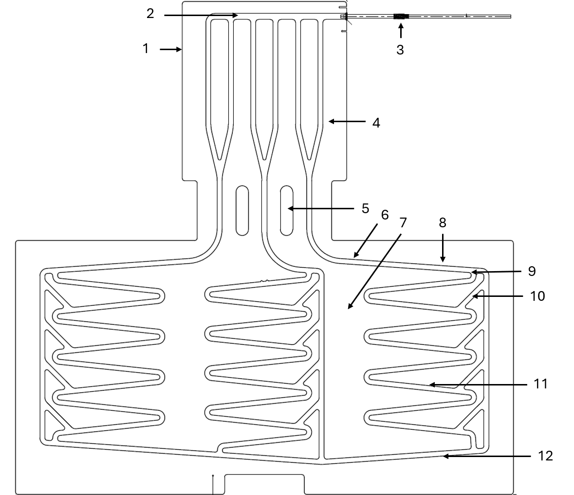
Figure 3: Thermosyphon design details
Refrigerant selection and charge volume
Since the thermosyphon always operates at the saturation point of the refrigerant, the operating pressure is defined by the saturation temperature of the thermosyphon. Flat-plate roll-bond thermosyphons have a maximum operating pressure based on the channel geometry. It is important to select a refrigerant that has saturation pressure at maximum CCE storage/transport temperature that is within the acceptable operating pressure of the roll bond construction. WHO PQS global warming potential (GWP) requirements and component commonality with the rest of the CCE also weigh into the refrigerant selection tradeoff.
The refrigerant volume is selected to maintain a pool of liquid at the bottom of the evaporator region. However, it must not be so full that it blocks the vapor bubbles from returning. Empirical testing indicates that maintaining approximately 20% liquid fill at the base of the evaporator region achieves reliable and efficient operation.
Performance tuning for low ambient temperatures
One challenge with WHO PQS CCE generally, and a thermosyphon-incorporating design specifically, is that when operating at very low ambient temperature (e.g. 5-10°C) there is so little thermal load on the appliance that the vaccine compartment will tend towards the temperature of the thermal battery. When using water/ice as the thermal battery, that means that the vaccine compartment can approach 0°C, unless a heater is implemented in the design.
To address this issue, we developed a method of non-linearly detuning the thermosyphon by adding a specific charge of noncondensible gas to the system upon commissioning. The noncondensible gas (dry nitrogen) has a lower density than the refrigerant vapor, and therefore rises above the refrigerant and exists as a "plug" in the very top region of the thermosyphon. This noncondensible gas plug effectively blocks off that top portion of the condenser region of the thermosyphon, which reduces the available surface area for the refrigerant to condense and reduces the thermal performance of the thermosyphon.
When the heat load and operating temperature of the thermosyphon increases, the higher-pressure rising refrigerant vapor is able to push up higher into the condensing region of the thermosyphon, compressing the nitrogen plug, thereby improving heat transfer. Using this method, we were able to engineer a temperature gradient across the thermosyphon at very low heat loads but still move heat efficiently at higher heat loads. This approach allows the system to maintain a 2°C operating vaccine temperature, even under negligible heat load, using a water-ice thermal battery. Figure 4 shows a comparison of the linear thermosyphon performance with only condensable gas vs. the desirable non-linear performance with the added condensable gas.
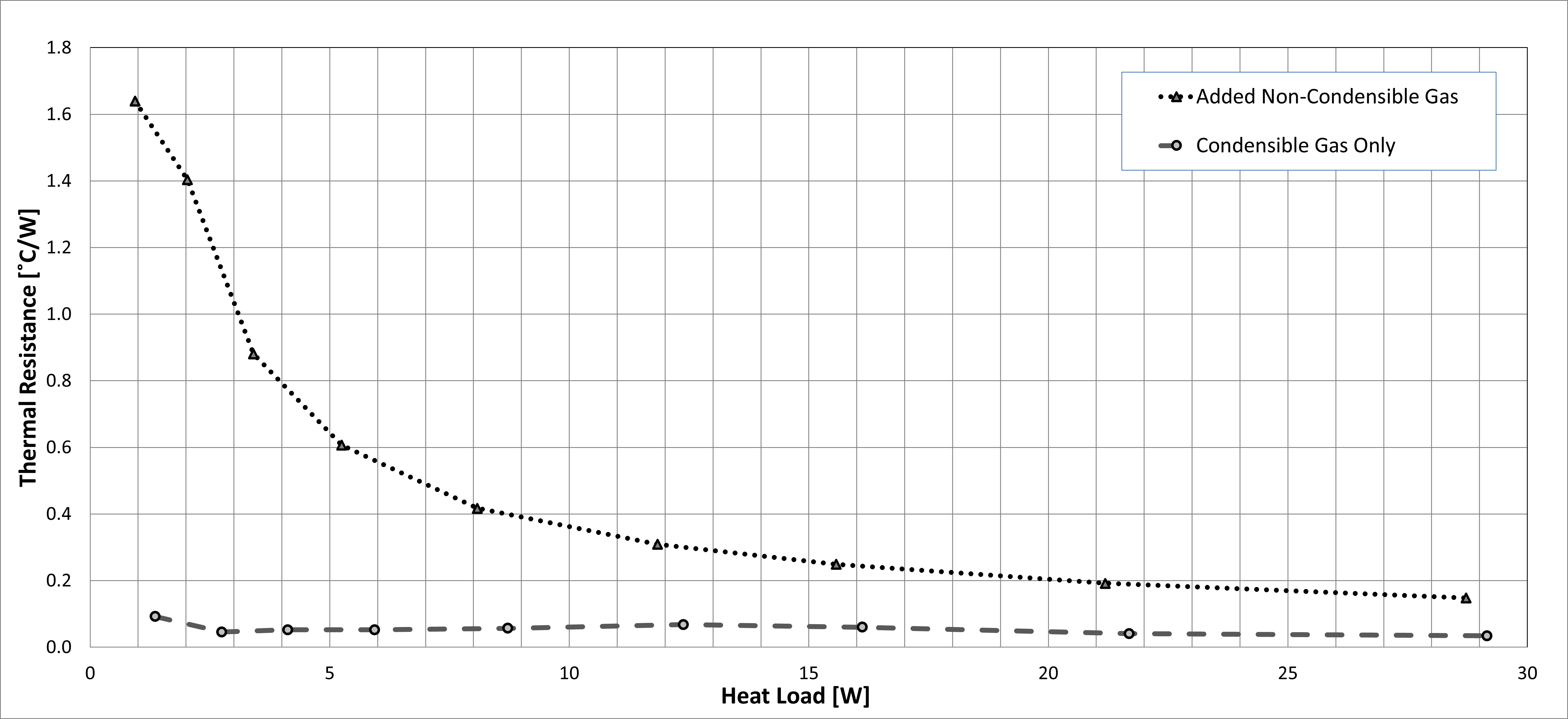
Figure 4: Measured effect of non-condensable gas addition to the syphon for detuning
For one system, the required nitrogen pressure was in the range of 40 Torr absolute (5.3 kPa). Each design will have a specific target amount of non-condensable gas that will need to be confirmed empirically. If there is significant seasonal variability in the factory ambient temperature, the non-condensable gas target pressure may need to be adjusted accordingly, to result in a consistent mass.
An effective charging process for the thermosyphon to reliably introduce the desired volume of non-condensable gas during manufacturing is:
- Before charging, verify a leak-free roll bond by removing the factory-installed plug to release the low-pressure (but higher than atmospheric pressure) dry gas that the roll bond was charged with at the factory. If some gas escapes, one can be sure that the roll-bond has been continuously pressurized since it left the factory.
- Charge the thermosyphon only after CCE foaming is complete and when the cabinet is in final assembly.
- Apply a high-quality vacuum pump and evacuate the thermosyphon. Pull it down to 0.5 Torr (0.067 kPa) or lower to ensure that there is no moisture present in the thermosyphon.
- Without introducing air or other non-condensable gases, charge the thermosyphon with a pressure of non-condensable gas that results in the desired nitrogen plug volume.
- Charge with the specified refrigerant volume.
- Clamp the stem, cut the tube, and braze the tip of the stem to permanently hermetically seal the thermosyphon.
- Leak check the brazed seal.
Ice compartment design
The ice tank in this architecture is engineered to be an efficient thermal battery while including a number of design considerations to minimize the risk of freezing vaccines. The fundamental approach to this ice compartment design is to freeze most of the water in the fridge for optimal holdover time, while always maintaining a water buffer between the thermosyphon condenser and the frozen ice. This water buffer prevents the thermosyphon from being exposed to freezing temperatures, adding another layer of protection against vaccine freezing. Critically, the compressor is controlled based on the ice state/temperature rather than the vaccine chamber temperature, with the thermosyphon physics controlling the vaccine chamber temperature. The below numbered bullets correspond to the numbered annotations in Figure 5.
- The refrigerant entry to the compressor-based evaporator for freezing water is oriented on the opposite side of the ice tank from where the thermosyphon is thermally coupled. This ensures that the coldest point of the ice is the farthest from the thermosyphon to reduce vaccine freezing risk.
- Correspondingly, the refrigerant exit is on the end of the evaporator closest to the thermosyphon.
- The evaporator cooling fins are oriented vertically and perpendicular to the wall of the ice tank that the thermosyphon is coupled to. This orientation ensures that when the ice is melting, the natural convection circulation of water is not impeded by the evaporator fins.
- Target ice geometry in frozen state
- Thermally conductive metal (Al) ice tank construction
- Water buffer maintained between ice block and the wall of the ice tank that the thermosyphon is coupled to.
- Temperature sensors. In this design, two temperature sensors are used to differentiate effectively between pre-nucleation subcooling and frozen ice. When the tank is full of liquid water the two sensors will report similar temperature values. When the temperature sensors approach the shutoff point due to the presence of ice, there will be a temperature difference between the two sensors due to the freezing of the ice being driven by the evaporator located to the left of the sensors in this graphic. Other control schemes are possible that could use a single sensor, or by sensing the phase change using a method other than temperature sensing (see Appendix A).
- Blue arrows indicate the direction of the circulation of water, which rises along the wall that the thermosyphon is coupled to as it is heated, and falls as it is cooled by the frozen ice block.
- Ultra-thin double-sided adhesive tape used to secure and to thermally couple the thermosyphon to the ice tank.
- Side view of flat plate thermosyphon
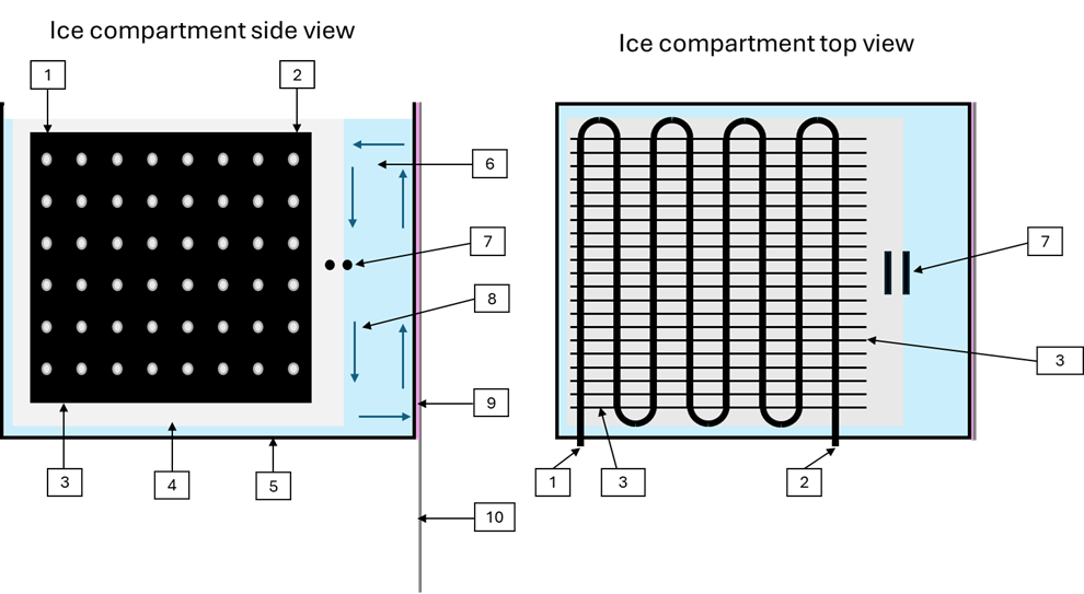
Figure 5: Ice tank geometry
Thermosyphon integration into refrigerator
The thermosyphon interface with the ice compartment and the vaccine compartment can be seen in the below images:

Figure 6: Flat side isometric view of thermosyphon
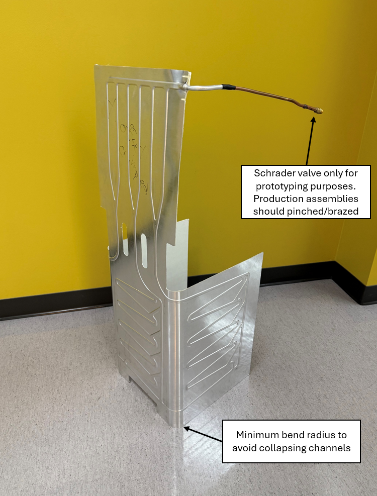
Figure 7: Channel pattern isometric view of thermosyphon
Reliability risks and mitigation strategies
A thermosyphon with added non-condensable gas for low-temperature management cannot be reliably evacuated and recharged in the field. Since the thermosyphon as described in this document is a foamed-in (non-replaceable) component, it is essential to minimize field failures through careful engineering. Below are a few of the potential failure modes and some methods that we have learned to mitigate them.
Submerged evaporator corrosion
While a submerged evaporator for the main compressor-driven refrigeration cycle is highly effective from a performance/efficiency perspective, there is an inherent risk of leaks due to corrosion that should be mitigated.
We do not recommend counting on an evaporator coating to mitigate corrosion due to the complex geometry of a tubed/finned evaporator. Since any flaw in the coating can result in corrosion being focused in that one location, an essentially perfect coating is required for reliable corrosion protection. Achieving this through standard manufacturing and quality control is impractical.
We have had the best results using a naturally corrosion-resistant material such as stainless steel for the evaporator. It is more expensive and less thermally conductive than aluminum, but in our experience the 5-10% increase in energy consumption and increased component price is justified to eliminate this component as a possible failure mode.
Submerged temperature sensor corrosion
As the control of ice freezing in the above implementation utilizes a submerged temperature sensor located at the interface between ice/water, the sensor undergoes frequent freeze/thaw cycles. This is a challenging operating condition, and a potential failure mode is corrosion due to water entering along the wires where the wire enters the metal sensor can/enclosure.
Known methods to address this are:
- Take extreme care with sensor design and manufacturing quality controls. Adding heat shrink to sensor leads where corrosion can occur, careful sealant selection, and rigorous quality controls in assembly can substantially address this risk.
- Use an extended metal can for the sensor, to move the wire/can interface above the surface level of the water.
- Embed a tube into the ice box that the sensor can be dropped into, so that the sensor is always in a dry environment.
Galvanic corrosion of refrigeration system tubing
Any place where two dissimilar metals touch is a potential point of galvanic corrosion. This has been observed in numerous CCE brands and models and in many scenarios. Extreme care should be taken in the design to either electrically isolate dissimilar metals from each other, or coat/seal them properly where a dissimilar metal connection is required. Minimizing stray electrical currents in the design by proper isolation is also strongly recommended.
Appendix A: Future design opportunities
The following are early-phase ideas that could potentially be useful, but where significant development would be required to bring these concepts to field readiness.
Chest-type fridge designs
While it has not been implemented or tested, it is theoretically possible to implement a chest-type design using a similar roll-bonded thermosyphon heat transfer system. Provided that the thermal battery is located slightly higher than the region of the vaccine compartment where heat is being removed, the gravity-based thermosyphon concept could be implemented.
Thermosyphon channel pattern optimizations
Non-condensable gas volume
A larger inactive volume at the top of the thermosyphon occupied by the non-condensable gas would reduce the sensitivity of the thermosyphon to error in the charge volume/pressure of the non-condensable gas.
We recommend care when considering adding volume to the top part of the thermosyphon as it is essential to know whether the volume will contain refrigerant or non-condensable gas during operation. For example, if any part of the channel pattern or the fill stem has a high point between two volumes, dense refrigerant may become trapped on the wrong side of that high point and occupy volume intended for non-condensable gas. Refrigerant stuck in such a section of tubing or channel could also have its own localized thermosyphon effect and transfer heat in an undesirable fashion.
Other innovative thermosyphon channel patterns
There are numerous concepts in patent application US15/219,592 for reservoir implementations in either the thermosyphon channel pattern or in adjacent containers to actively or passively store refrigerant or non-condensable gas to further customize the behavior of the thermosyphon in various operating conditions. Most of these more exotic concepts have not been implemented or tested, as they were not found to be necessary for a performant and reliable implementation.
Alternate methods for measuring ice state
It is a challenge to use a temperature sensor to control the main compressor system operation to achieve a desired ice state when freezing is removing latent heat rather than sensible heat, and significant ice state changes can occur with very small temperature changes. This issue is exacerbated by the fact that sub-zero temperatures are regularly observed before nucleation occurs. A simple “bang-bang” based control algorithm must have its lower set point substantially below zero so that the compressor is not shut off before ice forms during pre-nucleation subcooling. That makes it difficult to avoid over-freezing the ice once it does form.
One promising potential method for sensing the phase of the water is to use a capacitive level sensor, which could be tuned using a threshold adjustment to sense the phase of the water.
Resistivity/conductivity sensing is another possible option, but carries the reliability downside of submerged electrical contacts and possible measurement error over time due to water fouling or contact corrosion.
A method demonstrated at the benchtop level is to use two fused piezoelectric elements submerged in the ice tank. By exciting one element with a high-frequency alternating voltage and measuring the resulting output signal on the second element, the existence of ice can be sensed by the output voltage signal being much larger if the combined sensor can freely vibrate in liquid water.
Contact
Contact: Leo Chou
For more information, contact us about thermosyphon-based CCE architecture.