Solar power availability measurement for SDDs and energy harvesting
About this page
This page was written by the New Horizons engineering team, which operated until December 2025. First-person references ("we", "our") are the original authors'. A number of those authors are now working with Phoenix GH, which maintains this material and stands behind it. Questions and comments are welcome — please get in touch.
Introduction and open licensing
New Horizons developed a system to optimize power drawn from photovoltaic (PV) arrays used with solar direct-drive (SDD) vaccine refrigerators and optional “energy harvesting” systems. Energy harvesting controls (EHC) use excess solar power for non-cooling purposes when cooling is not required. This architecture has been used in PQS-prequalified vaccine fridge models carrying the MetaFridge brand.
As of the date of this publication, 2025-07-30, Tokitae LLC has abandoned any pursuit of patent protection for the MetaFridge system and will not assert or enforce any patent rights related to this implementation (US patent application US15/715,491, issued patent number US10707683B2). This dedication ensures that the community can freely use and build upon the system without restriction. This page and documentation within the downloads are licensed under the Creative Commons Attribution 4.0 International License, like most documentation on this web site. Hardware design files are licensed under the permissive CERN-OHL-P v2 Open Hardware License. Except for the third-party libraries, the attached code is released under the permissive MIT License.
Goals and features
A photovoltaic array has a characteristic curve of voltage and current. It is not a static curve, but as shown on the left axis and blue curves in Figure 1, it varies with insolation (solar intensity) and temperature. The power that can be drawn from an array varies depending on the loading conditions and is usually represented as a curve of power as a function of array voltage, as on the right axis and multicolor curves of Figure 1. Critically, the voltage at which maximum power is available varies with conditions. Figure 1 comes from the datasheet for the Renogy RNG-100D-SS 100 W solar panel. Typically, a solar MetaFridge would use 3 of these panels connected in parallel, or an equivalent 300 W panel.
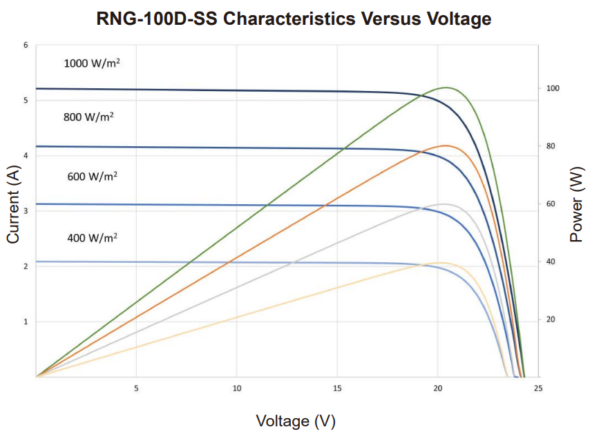
Figure 1: Current-Voltage and Power-Voltage curves for Renogy RNG-100D-SS 100 W solar panel, under standard test conditions at 25°C.
Maximum peak power tracking (MPPT) of a photovoltaic array is a well-developed art, designed to maximize power production from relatively expensive components. A common approach is to perturb the operating voltage, measure the change in power drawn from the array, and either keep changing the voltage in the same direction or reverse, depending on the measured change. This technique works well to keep operation near the peak, though it can be fooled if the array has local maxima due to partial shading or damaged cells. There are many techniques to optimize performance further.
Conventional MPPT approaches work well when the load is a well-controlled voltage like the mains grid or a battery. However, it is less well suited to operation of SDDs, which operate their compressors directly from the PV array without significant energy storage in batteries. Some considerations are:
- Some compressors have a rating for the number of restarts per hour. If that is the case for the compressor being used, the design should ensure there is enough power available to start before making the attempt.
- Some refrigeration systems also need a delay period between compressor stop and restart to avoid stressing the compressor with back pressure. To maximize cooling, unnecessary stops should be avoided.
- The maximum compressor load is usually much lower than the peak power available from the array so that the system may operate in variable sun conditions.
- Cloud cover can suddenly reduce available power. This drop may collapse array voltage and stop a running compressor.
- Energy harvesting loads can have large transient power draw from people attaching loads or other behaviors. A sudden added load can also cause the array voltage to drop.
The system we developed has the following features to address these considerations:
- The system periodically monitors the power available from the array.
- If cooling is needed, the system will not attempt to start the compressor until there is enough power available.
- The variable-speed compressor is not operated at the peak power of the array. Rather, the system chooses a power level to maintain a buffer margin between consumed power and available power. The margin allows time for the compressor to slow during most cloud events, thus avoiding a stop.
- When the compressor is idle, the energy harvesting circuit activates its loads. If there are multiple loads, they are enabled according to expected maximum power.
- If the compressor is running at full speed and there is excess power available, the system enables energy harvesting loads with consideration for their maximum possible power draw. It keeps the sum of all enabled maximum power draws below the available power by the buffer margin. This scheme prioritizes cooling but also harvests more excess energy than one that does not operate compressor and energy harvesting at the same time.
The next section explains the implementation in more detail.
Operating principles
Power system hardware
Figure 2 below and the downloadable PDF show a simplified power diagram of the power circuit board. On the lower left are the photovoltaic input and its monitoring block. On the upper left are the mains (AC) power input, though that is not a topic of this web page. The power system is managed by a single microcontroller. It continuously measures the power drawn from the PV array by all the loads in the system, which are:
- The monitoring electronics and its battery charger (including the “main board”, which is connected via the connector in the center of the diagram).
- The compressor/condenser fan, also in the middle of the diagram.
- The compressor, connected at the upper right.
- Three energy harvesting load output ports: 5 V, 12 V, and a flexible voltage output. These are on the right side of the diagram.
- Finally, there is the available power assessment circuit, which is near the PV input and power monitor.
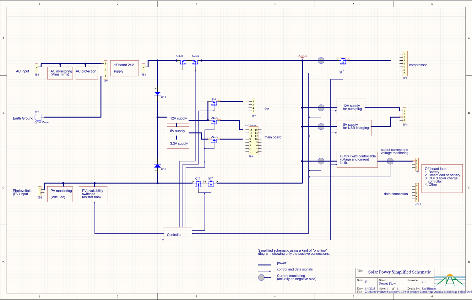
Figure 2: Block diagram of power system
Available power assessment
When the compressor is running, it is possible to vary the compressor speed to adjust the power draw to assess whether it is close to the array’s present peak power. To maintain a buffer in available power, we operate the compressor to the right of the peak of the power-voltage curve, as shown in Figure 3. In the event of shading, the operating voltage will change a little but it is much less likely to collapse below the minimum compressor operating voltage than if operating at or to the left of the peak.
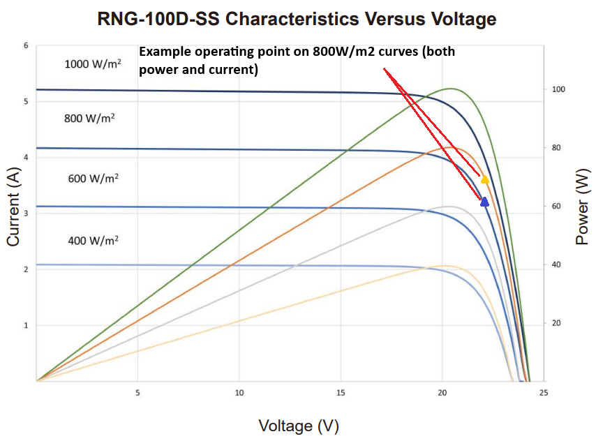
Figure 3: Power-voltage curve with operating point marked
The primary function of the available power assessment circuit is to determine whether it is possible to start the compressor. This circuit consists of a power resistor or resistors that can be switched across the PV input, thus drawing power. In our implementation, there are 6 binary weighted resistors and 6 FET switches. Binary weighting (each successive resistor draws approximately twice the power of the previous one) allows us to apply a wide range of loads in 63 increments (zero load is the 64th step). The circuit schematic is in Figure 4; U1 is a level-translator and FET gate driver circuit.
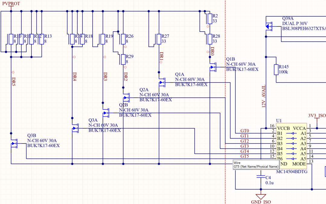
Figure 4: Available power measurement circuit resistor bank
The microcontroller periodically starts an available power assessment, known as a “full assessment” for reasons that will become clear soon. Starting from zero load, each step of the 64 load levels is switched on briefly. The load is kept on long enough for any transient to settle, and then the array voltage and current are measured. Immediately thereafter, the load is switched off to minimize power consumption and self-heating. The microcontroller calculates the slope of the power-voltage curve, and if it is sufficiently high, it switches on the next loading level and repeats the process. Once the slope becomes flatter than a predetermined threshold or changes sign, the assessment is terminated, see example in Figure 5.
The available power is defined as the last load level before the slope threshold is met, or the level before the slope changes direction. The assessment may not reach the peak power of the array, especially in full sun conditions. But it is sufficient to determine if the compressor may be started or energy harvesting enabled.
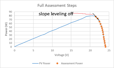
Figure 5: Example of assessment steps on the power-voltage curve, showing lower slope that ends the assessment process.
Other implementations may use more resistors and switches to gain a greater degree of fidelity of available power. They may also use fewer; for example, a single resistor could determine whether there is sufficient power available to start the compressor.
The system begins compressor operation at its lowest speed and power. If the last assessment indicated that there should be sufficient power for higher-speed operation, the microcontroller commands to increase the speed by an increment. Once the compressor reaches the new target speed the array operating point is compared to the operating point after start. If the slope of the power-voltage curve is sufficiently steep, it attempts another speed increment. Conversely, if the slope is too flat or has changed sign, it slows down the compressor to keep it running. This continual adjustment happens at a faster rate (every 2 seconds) than the periodic full assessments with the load bank (typically every 10 seconds).
The system also uses a “quick assessment” between full assessments. Once the compressor reaches full speed, these assessments can provide rapid feedback. This process turns on the lowest loading level resistor to measure the slope of the power-voltage curve. If it appears that the system is operating too close to the array’s peak power level, it will slow the compressor. The microcontroller uses a conservative strategy—small speed increases and larger decreases—to reduce the risk of stops.
Energy harvesting
The microcontroller continues to perform full assessments as the compressor is running. Because the starting point is the operating compressor power, fewer steps are needed to reach the termination point. If the available power is sufficiently high, the microcontroller will enable energy harvesting load(s). As noted above, “sufficiently high” means that the sum of the compressor’s power, maximum EHC power, and buffer must be less than the available power.
When multiple EHC loads are available, the system must prioritize which to enable first. Several different prioritization schemes could be chosen, for instance: (1) enable the small loads like USB ports first because that will help health center staff keep their mobile devices charged, or (2) enable high-power port(s) first because they are used to charge battery-powered lights or healthcare equipment. Regardless of the prioritization policy, the above comparison must hold. The microcontroller continues to monitor available power, and if the above comparison becomes false, the microcontroller will disable EHC port(s) until it is true again.
The system follows a similar strategy when cooling is not required. The microcontroller can enable EHC output(s) at lower available power levels since the compressor is not running. It may also be less conservative because it does not need to protect the primary function of the SDD: maximizing cooling. It may use a smaller buffer margin, enable multiple outputs that have the possibility of drawing more than the available power, or allow loads to manage the risk of voltage collapse. It may prioritize multiple loads differently than it would if the compressor were running.
Smart energy harvesting loads
Energy harvesting loads containing their own microcontrollers can coordinate with the solar power board to share the power available from a single PV array. New Horizons built a prototype icepack freezer designed to operate from the solar power board’s flexible voltage and current energy harvesting output. The output includes a communication port that allows coordination between devices.
In operation, the solar power board would enable the power output, but request that the freezer not start its compressor until there was sufficient power available. To help the freezer start, the system can temporarily slow the main compressor and free up power. When both compressors were running, the solar power board would request a maximum freezer power draw to minimize the chance of stopping both compressors. When the refrigerator’s compressor was not needed, the freezer was free to choose its own power level.
Potential challenges and solutions
We have come across several challenges during the development process and in deployments.
Heating
The resistor-based assessment process generates heat when loading the PV array. When insolation is high, the assessment uses all the steps to reach the highest wattage end of the resistor bank, creating the most heat. Sometimes this also happens when ambient temperatures are high, potentially raising the circuit board temperature to concerning levels. Some of the strategies we have found to mitigate these effects are:
- Keep the resistor connected only for the minimum time necessary to let transients settle and capture the voltage and current measurement.
- Monitor the circuit board temperature near the resistors and increase the interval between assessments as the temperature rises. This reduces the average power dissipated by the resistor bank at the expense of slower responses to changes in insolation.
- Reduce heat by skipping some assessment steps—especially in high-slope regions where detailed resolution is unnecessary. In particular, one can skip steps in the high-slope areas where resolution is less necessary, only going step-by-step when nearing the peak.
DC power supplies
Operating an SDD with this power availability circuit from DC power supplies comes with some challenges. AC/DC converters may be used to turn a solar fridge into a mains-powered fridge. In a development and test environment, laboratory power supplies offer a convenient way to power a fridge. The challenge is that these supplies tend to have rectangular current/voltage curves rather than smoothly varying curves. The power/voltage curve sharply transitions at the maximum current limit, creating a slope discontinuity. Because the available power algorithm searches for a low slope, it can be confused by this power source characteristic.
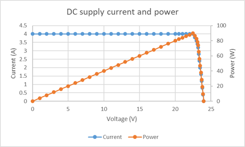
Figure 6: Example DC power supply current-voltage and power-voltage curves
Some solutions we have explored and implemented: If the fridge configuration is known, such as when creating a mains fridge from an SDD, the AC/DC converter’s maximum power will also be known. In this case, configure the firmware with the known power limit and skip the assessment process.
For example, the MetaFridge SDD has both PV and mains inputs. The mains input is converted to DC to run the compressor with a built-in converter. When the microcontroller switches between power inputs, it changes the algorithms used to control the compressor and energy harvesting outputs accordingly.
Another solution is to use the assessment process to detect the presence of a DC power supply. If in the initial phases of a full assessment the slope of the power/voltage curve is steeper than some threshold, one can be certain that the system is not operating on PV. One can use a different algorithm to assess the capacity of the supply and sequence the compressor and EHC loads.
In some contexts, it may make sense to only do this once and assume that the power supply is a fixed capacity. In other situations, such as the WHO/PQS/E003/RF05-VP.x verification protocol for SDD prequalification, the power supply’s capacity varies over time to simulate solar insolation throughout the day. It would be advantageous to periodically assess power availability, but with an assessment algorithm designed for DC supplies.
Downloads
-
Printed circuit board design files (.zip) These are Altium source files and the output files needed for fabrication (Gerber, Bill of Materials, etc.). The archive also includes the "auxiliary" board, which holds fridge external connectors for energy harvesting outputs.
Contact
Contact: Rod Hinman
For more information, contact us about solar power availability.